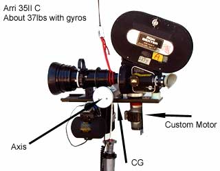
Arri 35 Gyro Assisted Rigs
Here are some examples of different
ways to use Kenyon gyros with larger cameras. I would recommend that you study
all the material in this section and in Inertial Camera Stabilization before
building anything. There may be easier solutions. Building simple prototypes
are a great tool for discovering, balance, clearance and mounting problems.
Consider making mock cameras and gyros of the same weight, mounting thread and
CG positions for prototyping.
Also consider using the lightest
cameras available such as an Aaton or a modified II C. The gyro noise limits
sound recording close to camera. Register pins are not relevant unless shooting
plates. The first two examples below of combined camera, zoom lens, dovetail
and gyros weight about 35 lbs. "More professional" looking rigs could
include small U-joints, rods, cables instead of the nylon cords, and of course
anodized parts. But consider that the additional weight of U-joints defeats
the stabilization effect of the gyros.
I have made no provision here for
weight transfer as the film travels in the magazines. This can be manual or
automatic as the camera rolls with some innovation. The weight should travel
in line with the magazine spindles. The weight transfer when the zoom position
is changed seems too small to be a problem. You will have to work out cable
problems to camera, video assist and gyros. I like head mounted viewfinders,
but viewfinders can be mounted on the camera system. Just keep the weight down
to a minimum.
The first two configurations can
be supported from below or above with almost the same hardware.
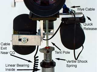
1. Arri 35 with Zoom Supported from
Below
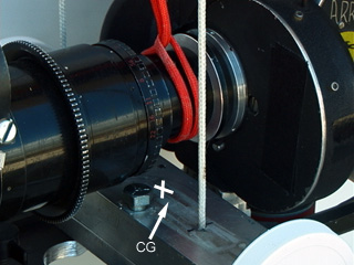
I used these custom dovetails for
years before Arri went to matte box rods. It is helpful if you can provide some
CG adjustment right at the CG where adjusting is most sensitive. You should
also provide fine tuning CG adjustment at each gyro. In this case the gyros
are located low so that the combined CG and support point is just below the
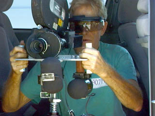
camera lens. There is no zoom motor control on this prototype. We do moving
tests with equally weighted mock-ups and a consumer camcorder. The unit is controlled
with 2 hands in line on the CG axis. A zoom control would replace the round
handle on the right side. Note the loose safety cord from above. The motor shown
is home made and we have used for years. It is constant speed from 1/4 FPS to
50 FPS and runs off 30 volts. Today there are many good after-market motors
made for the Arri II models. We made our own when there were only the three
marginal motors made by Arri.
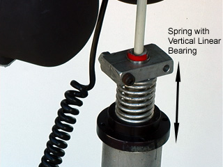
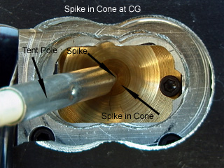
A spring and a shaft in a vertical
linear bearing, damp the vertical motions. A fiberglass tent pole damps the
horizontal motions with a spike in a support socket under the lens on the camera
system.
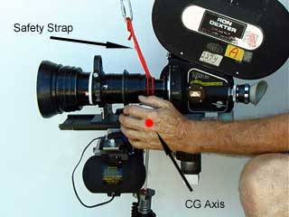
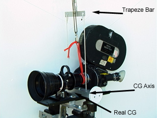
2.Arri 35 with Zoom and Support from
Above
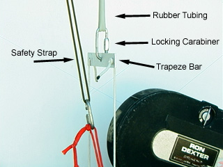
The same hardware as the above example
can be used for hanging by rubber tubing, springs or bunji from above. Holes
just big enough for the nylon cord are drilled in line with the CG axis and
the cords are attached to the trapeze bar above. Tie secure knots in the nylon
cord and check periodically for wear. Make smooth edges on the holes to avoid
fraying the cord. The CG is in the same place as the above rig. The trapeze
transfers the CG from the holes back to the center. Note the loose safety strap
to above.
3. Other Variations
You can build versions with the gyros
on each side of the camera with a trapeze from above. Make sure that you follow
all the "Gyro Basics" as close as you can. The transfer of weight
of the film as it is used, has been solved by the helicopter ball mount. For
short shots, a sliding weight would do just fine if you adjust it between takes.
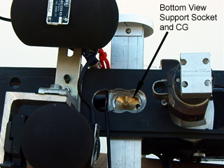
For standard matte box rod systems, the support socket for the tent pole spike
can be between and above the rods and just below the lens which is close enough
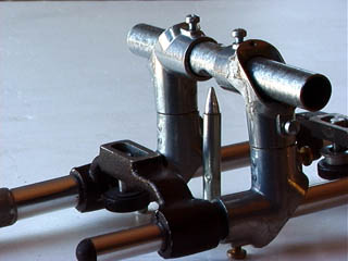
to the camera / lens CG.
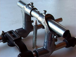
These are 1/2" EMT elbows with
sleeves for the 15mm matte box rods.
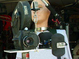
4. Arri with Hard Lens Hung from
Above
Here the combined camera, rig and
gyros weights about 25 lbs. The gyros are close and the unit is compact for
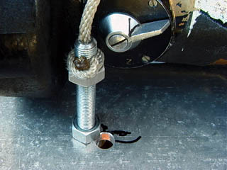
a (Body Cam) backpack support. The GC is adjustable up and down with the 3/8"
bolt holding the nylon cord. The gyros can move side to side and back and forth
for dynamic balancing. Here the gyros are the factory recommended, 1/2 the weight
of the camera, and are very effective. The mannequin is handy for adjusting
everything before putting the pack on an operator.
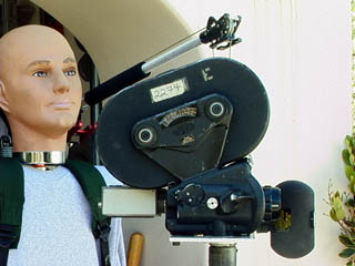
5. Arri with Hard Lens Supported from Below
This is a slight modification of
the above rig. The gyros are mounted on the bottom of the plate and the CG is
now in the middle of the 1/4" plate. A detent socket is drilled with a
1/2" drill bit almost all the way through the plate to make a socket for
a spike from below. A larger socket is recommended so the spike can't jump out
of the socket during a violent move by the vehicle.
6. Arri with Zoom Hung from Above
with Gyros at Top
I built an Arri with zoom prototype
similar to the Betacam model with the gyros above the lens. The saddle under
the camera allows attachment to the CG above the base of the camera. No matter
where the gyros are attached, get them close to the mass of the camera. The
CG often ends up somewhere in the middle of the camera body. Putting the gyros
forward and high, places the CG closer to the viewfinder. When the camera pans
and tilts the operator's eye will not have to move much. This is an issue especially
when the operator is sitting behind the camera. Refer to Gyro
Betacam Type Rig.
The "trapeze" transfers
the CG from inside the camera body to above the camera. It is attached to an
above support and isolation system, in this case rubber tubing. There is no
zoom control shown here and should be for the right hand. It should be centered
in line with the CG of the system. The trapeze bar above should be balanced
and drilled for the horizontal CG ONLY AFTER all elements are attached to the
camera system.
© Copyright 1999-2004 Ron Dexter. All Rights Reserved.