Kenyon Gyro Examples for Lightweight Camcorders
There is also some new material here that I recently discovered while working with another Kenyon Gyro user. I don't put stuff up on the site myself and this section somehow got overlooked. The VX 1000 designs shown here will work even better with cameras with flip out finders like the VX 2000, TRV 900, PD-150, GL1 and others. The horizontal board or plate would have to be a bit wider for the finder to flip out. The gyro can go on either side of the CG and support point.
I highly recommend that you refer back to all the Kenyon guidelines and study my other designs as you design and build a rig. It is very important to understand all the principles, problems and solutions. If you apply them as you build a prototype you will save you time, materials and frustration.
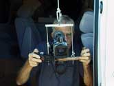
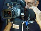
This is about as simple as it gets, but works very well. With one Kenyon there is no horizon roll stabilization, but your hands can help make those corrections. We shot full digital zoom out the side of our van. (Read safety notice about shooting from vehicles in this same section.)
Operating (framing a shot) hand held at this extreme focal length is difficult from a moving vehicle, but the images we got were very steady. The in-camera stabilizer was turned off. Try once you get a solid framing on a distant object for a few seconds, zooming back wide. It will be an impressive 20 to one zoom using the digital zoom. If you have other lighter or heavier cameras or ones with different mounting holes, you might need to make one of the versions described in this section.
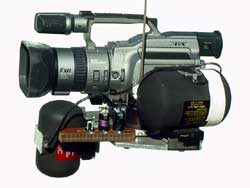
The horizontal plate between the camera and the stabilizer allows the CG of the combined camera and gyro to be supported at the CG of the combined two. Fortunately the VX 1000 has its tripod mounting thread exactly below the CG of the camera. The trapeze cords are attached on the CG axis of the combined camera and stabilizer. (Flip out screen cameras will not balance the same and will need adjustment for every different position of the screen.) It is important that the upper trapeze bar has outer holes the same width as the holes in the cradle. Drill the center hole where the bunji attaches after checking the whole unit for horizontal balance with the viewing screen in position. Make sure the battery tape and ay other accessories are installed.
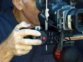
The left hand is placed symmetrically on the other side of the camera. This unit does not remove horizon roll because there is only one gyro, but works quite well. That would take an additional stabilizer.
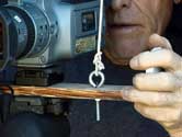
I made this "sport finder" eyepiece with a 25-mm magnifier lens in a piece of PVC. You might make a prototype out of film cassettes or plastic medicine bottles. The shield around the lens blocks stray light to your eye when the camera is away from your eye. Your eye should NOT touch the camera when shooting!
You will probably need remote zoom control. I use the Canon external zoom control, which puts the zoom rocker in the same relative position as it is normally to the fingers on the VX-1000. (I don' think that the newer fancy and expensive zoom controls are any better than the Canon which will work with any camera with "L" control. Supporting the forearms with rubber tubing helps reduce arm fatigue. See "Operating and Rigging" .
This layout would have to be a bit different for a flip-out finder. The camera could be back a bit. The horizontal gyro a little farther from the camera.
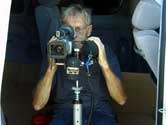
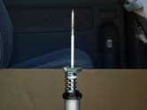
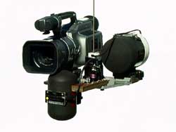
I built this before I had a second KS-4 and used a KS-8, which a bit is overkill for the VX1000. A K-4 in place of the K-8 would LOWER the CG. The CG in this arrangement is inside the shiny black tube with a white top between the camera and K-8. The second vertical KS-4 Kenyon stabilizes horizon roll. This is much more complicated but will work when support from above is not available. A cup at the CG rests on a spike on a fiberglass tent pole with a spike rests in a cup right at the CG provides side to side isolation. The vertical linear Tompson bearing (black ring below spring) isolates vertical motions. The isolator base plate, not shown, has to be rigidly and well attached to the floor of the vehicle.
Fortunately the palm of your right hand position is on the horizontal CG axis and the camera's zoom control rocker is very conveniently placed just above it
The additional weight under the plate has moved the CG down and the cords through the plate. The second gyro adjusts up and down to place the CG in the black cup above the plate. Now the guidance handles are also symmetrical to the plate.
|
|
In working with Glenn Schneider of the University of Arizona Astronomy Department designing a rig for 4 cameras to shoot the solar Eclipse, Glenn wanted a "hands-off" rig to shoot the eclipse at a angle of 15 degrees above the horizon. He supported the rig ABOVE the CG a little so that the rig hung looking up by 15 degrees. Vertical designs like Steadicam © have the support point above the CG so that gravity helps keep the horizon. Glenn went further and used gravity to tilt the whole rig up by 15 degrees. I was concerned about not attaching it at the CG. BUT this worked well and the gyros kept the rig stationary on target (the sun) for the time necessary to photograph the eclipse.
Now that opens up a whole new possibility of making rigs that can compensate for a level horizon or looking up or down using gravity and letting the gyros do their work.
If we use all the principles states in the gyro stabilization section, EXCEPT place the support above the CG, new applications are possible. Let me state though that one should be cautious to not violate any of the principles stated to far as the effect of the gyros will be compromised.
Here is a great example of problem solving breaking new ground.
© Copyright 2004 Ron Dexter. All Rights Reserved.